The centrifuge calibration procedure is a critical maintenance task involving the precise verification of rotational speed and timer accuracy to ensure experimental reproducibility and lab safety. While it supports the broader objectives of maintaining high-precision lab equipment, mastering the internal verification process allows technicians to maintain compliance between professional certifications. This guide provides the technical steps required to use photo-tachometers and stopwatches for routine internal performance qualification, ensuring your lab remains audit-ready at all times.
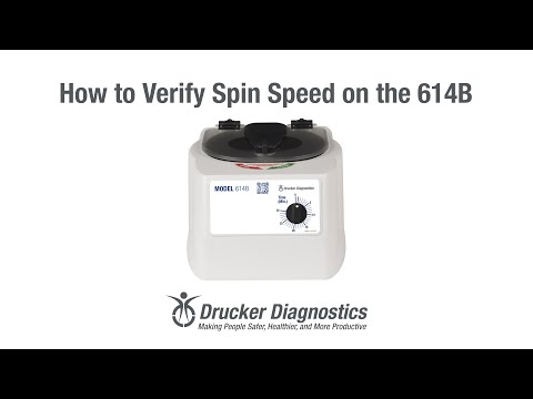
Image taken from the YouTube channel Drucker Diagnostics , from the video titled How to Verify Spin Speed on the 614B .
Pre-Calibration Safety and Equipment Setup
Before starting a centrifuge calibration procedure, you must verify the structural integrity of the rotor and the functionality of the lid-locking mechanism to prevent high-speed hazards.
The safety of the technician is the primary concern when dealing with high-velocity laboratory equipment. Before any electrical or mechanical measurements begin, a thorough physical inspection of the unit is mandatory. This involves checking the rotor for micro-fractures, chemical corrosion, or debris that could lead to an imbalance during high-speed rotation.
Essential Tools for Verification
To perform a reliable internal Preparation check, you must gather specialized equipment that carries current NIST-traceable certification. Using uncalibrated tools to verify another instrument invalidates the entire process and risks regulatory non-compliance.
- NIST-traceable photo-tachometer
- Reflective tape for optical measurements
- Calibrated stopwatch with 0.1-second resolution
- Safety goggles and personal protective equipment
Ensure that the photo-tachometer has sufficient battery life and that the reflective tape is adhesive enough to withstand the centrifugal forces generated at the maximum RPM of the specific model being tested.
Safety Interlock Inspection
The lid-locking mechanism is the most critical safety feature of any modern centrifuge. During the Preparation phase, verify that the unit cannot be started while the lid is open. Furthermore, confirm that the lid remains locked until the rotor has come to a complete standstill.
If the emergency release trigger is accessible, test its functionality to ensure it operates correctly in the event of a power failure. Document any resistance in the hinge or latching mechanism immediately, as these mechanical issues can lead to measurement variances during the speed verification phase.
Takeaway: Proper preparation prevents mechanical failure and measurement error.
With safety confirmed, we move to the technical measurement of rotational speed.
Step-by-Step Speed Verification Using a Photo-Tachometer
To calibrate centrifuge speed, apply reflective tape to the rotor and use a photo-tachometer to measure the actual RPM against the programmed set points at three distinct ranges.
The accuracy of rotational speed is fundamental to the relative centrifugal force (RCF) applied to samples. To begin Speed Verification, the centrifuge must be clean and empty, or balanced with dummy loads if required by the manufacturer’s service manual. The photo-tachometer works by emitting a light beam and measuring the frequency of reflections from a specific point on the rotor.
Applying Reflective Tape for Accuracy
For the most precise Speed Verification readings, place a small piece of reflective tape (approximately 0.5 cm²) on a clean, dark surface of the rotor. The contrast between the dark rotor body and the reflective tape allows the optical sensor to register a clean pulse for every rotation.
Position the tachometer outside the centrifuge, aiming it through the clear viewing port in the lid. If the lid does not have a viewing port, you must use the manufacturer-approved access point or internal sensor interface to capture the data without bypassing safety interlocks.
Measuring Low, Medium, and High RPM
To ensure linearity across the instrument's operational spectrum, perform measurements at three set points. Usually, this involves testing at the lower limit, the midpoint, and the maximum rated speed of the rotor. Record the stabilized reading at each level after the centrifuge has reached its target velocity.
| RPM Set Point | Measured Value (Tachometer) | Acceptable Deviation (+/- 2%) |
|---|---|---|
| 1,000 RPM | 998 RPM | 980 - 1,020 RPM |
| 5,000 RPM | 5,015 RPM | 4,900 - 5,100 RPM |
| 10,000 RPM | 9,950 RPM | 9,800 - 10,200 RPM |
Maintain the tachometer at a steady angle and distance as recommended by the device manufacturer. Sudden movements of the tachometer during the reading can cause false spikes or drops in the recorded RPM data.
Takeaway: Multi-point verification ensures linear accuracy across the equipment's full range.
After verifying speed, the focus shifts to the temporal accuracy of the equipment's internal clock.
Timer Accuracy and Operational Tolerance Limits
Timer verification requires a NIST-traceable stopwatch to measure the interval from the moment the rotor reaches set speed until the braking cycle begins.
In clinical and research settings, the duration of centrifugation is just as critical as the speed. A Time Verification check ensures that the internal electronics are properly triggering the start and end of the cycle. Inconsistent timing can lead to over-processing or under-processing of sensitive biological samples, affecting the integrity of the results.
Stopwatch Synchronization Protocols
The standard protocol for Time Verification involves synchronizing a manual, calibrated stopwatch with the centrifuge's digital display. The technician should start the stopwatch exactly when the centrifuge indicates it has reached the programmed RPM. This accounts for the "ramp-up" time, which is often excluded from the actual spin duration in high-end models.
Observe the centrifuge closely as it nears the end of the cycle. Stop the manual timer the moment the drive motor disengages and the braking sequence begins. This provides the most accurate reflection of the "at-speed" time.
Calculating Percentage of Deviation
Once the data is collected for multiple intervals, you must calculate the percentage of deviation to see if the unit falls within the laboratory's established tolerance limits. Most Quality Assurance (QA) programs set a maximum allowable error of 1% or 5 seconds, whichever is greater.
- Short duration test: 5 minutes
- Routine duration test: 10 minutes
- Extended duration test: 30 minutes
To calculate deviation, subtract the measured time from the set time, divide by the set time, and multiply by 100. Consistent deviations across all tests may indicate a failing control board or an aging internal oscillator that requires professional service.
Takeaway: Most GLP standards require timer accuracy within +/- 1% of the set duration.
Accurate measurements are only valuable if they are documented according to regulatory standards.
Documentation for Audit Compliance and GLP
Every centrifuge calibration procedure must be documented with the instrument ID, date of testing, NIST-traceable tool serial numbers, and the pass/fail status based on predefined tolerances.
In a regulated environment, an action that is not documented is considered an action that never happened. Proper Documentation serves as the legal and scientific proof that the equipment was performing within specifications at the time of use. This is vital for Good Laboratory Practice (GLP) and maintaining ISO accreditation.
Creating a Calibration Log
A standardized Documentation template should be used for every piece of equipment. This log should include the unique asset number of the centrifuge, the model and serial number of the tachometer used, and the environmental conditions of the lab, such as temperature and humidity, if they impact the equipment's operation.
The log must be signed and dated by the technician performing the verification and counter-signed by a Quality Manager or Laboratory Supervisor. These records should be stored in a centralized equipment file, easily accessible during a snap audit or a scheduled regulatory inspection.
Handling Out-of-Tolerance Results
If a centrifuge fails to meet its required speed or time accuracy, it must be immediately labeled with an "Out of Service" or "Do Not Use" tag. The Documentation must reflect the failure, the date the unit was removed from service, and the subsequent corrective actions taken.
The technician should also perform an impact assessment to determine if samples processed on the machine since the last successful verification were compromised. This proactive approach to data integrity is a cornerstone of modern laboratory quality management systems.
Takeaway: Meticulous records are the only proof of compliance during a lab audit.
Understanding when to perform these steps internally versus calling a professional is vital for total quality management.
Internal Verification vs. Professional Certification
While internal verification ensures ongoing performance, it does not replace the standard centrifuge calibration procedure performed by accredited technicians for ISO/IEC 17025 certification.
Laboratories often struggle to differentiate between Performance Qualification (PQ) and full metrological calibration. An internal Compliance Strategy usually involves frequent, simplified checks to ensure the machine hasn't drifted. However, these checks are only as good as the internal SOP and the skill of the staff performing them.
The Role of Internal Performance Qualification
Internal checks serve as a critical bridge between annual professional visits. By performing a simplified centrifuge calibration procedure on a quarterly or monthly basis, labs can catch minor issues before they become major failures. This frequent monitoring reduces the risk of long-term data skew and provides a higher level of confidence in daily experimental results.
Staff should be trained specifically on the internal SOP to ensure repeatability. If three different technicians get three different results on the same machine, the internal Compliance Strategy is flawed and needs revision to standardize the measurement technique.
When to Schedule Professional Calibration
Professional calibration involves much more than just speed and time checks; it includes electrical safety testing, motor brush inspection, and vibration analysis. It is essential to follow the standard centrifuge calibration procedure performed by an ISO 17025 accredited provider at least once per year or after any major repair.
External professionals provide a certificate of calibration that carries legal weight and satisfies the most stringent regulatory bodies, such as the FDA or CLIA. These certificates include the uncertainty of measurement, which is a mathematical requirement for many high-level certifications that internal checks cannot satisfy.
Takeaway: Use internal checks to bridge the gap between annual professional certifications.
Summary of internal verification benefits follows.
Visualizing the alignment of the photo-tachometer with the rotor's reflective tape is essential for accurate RPM readings. Watch the following demonstration to see the internal verification process in action, ensuring your manual measurements align with digital readouts.
Video: Performing Internal Centrifuge Speed Checks
Centrifuge Calibration Procedure FAQ
Explore common questions regarding the frequency, tools, and regulatory requirements of the centrifuge calibration procedure.
How often should internal centrifuge verification be performed?
Monthly or quarterly checks are recommended between annual professional calibrations. This frequency ensures that any drift in speed or timing is identified before it impacts experimental results.
Consistent internal monitoring bridges the gap between comprehensive annual ISO certifications and maintains ongoing quality compliance.
What is the allowable tolerance for centrifuge speed?
The allowable tolerance for centrifuge speed is typically +/- 5% of the set RPM, although internal lab protocols may mandate stricter requirements. Clinical or research laboratories often define specific performance qualifications based on the sensitivity of their assays.
If the deviation exceeds this threshold during internal verification, the unit must be removed from service for professional adjustment or repair.
Do I need NIST-traceable tools for internal checks?
Yes, audit compliance requires that all internal verification tools, such as photo-tachometers, are NIST-traceable and currently calibrated. Using non-certified equipment for internal verification invalidates the quality control data and can lead to non-conformance during regulatory audits.
Technicians must document the serial numbers and expiration dates of the master tools used during the verification procedure to ensure full data integrity.
Executing a consistent centrifuge calibration procedure ensures that your laboratory results remain valid and your equipment stays within operational tolerances. By integrating these internal verification steps with the professional standards detailed in our Centrifuge Calibration: Ensuring Lab Accuracy [2024 Guide], lab managers can create a robust quality control framework. Document every check meticulously to facilitate a seamless transition during your next full-scale professional audit and to maintain the highest level of scientific integrity.